Interim Report Section 3: Inquiry Issues and Recommendations
3.5 New Building Technologies
Alternative building technologies have been and are being developed, which enable the damage sustained in major earthquakes to be reduced. The Royal Commission has received and published on its website a report entitled ‘Base Isolation and Damage-Resistant Technologies for Improved Seismic Performance of Buildings’, which has been prepared for it by Professor Andrew Buchanan and others of the University of Canterbury. The Royal Commission considers that structural engineers and architects involved in the rebuild of Christchurch should be aware of the content of the report. It is likely that adoption of one or more of these new technologies would result in improved seismic performance of new buildings in Christchurch.
Several new technologies are described in the report. The first is base isolation, which has been used for a number of new buildings and the seismic retrofit of existing structures. This methodology involves the incorporation in the structure of devices which allow the building to move relative to the ground. It is probably not accurate to describe the methodology as new. The lead rubber bearing, used in the majority of cases, was developed in 1974 by Bill Robinson, a New Zealander, who at the time worked for the DSIR in Wellington. Lead rubber bearings have been used extensively around the world and it is now estimated that buildings worth more than US$100 billion have been base-isolated using these bearings. In New Zealand, lead rubber bearings were used for base isolation of the William Clayton building in Wellington. This was the first building to be base-isolated using this technique. Such bearings have subsequently been used in New Zealand in the construction of Te Papa, the new Wellington Hospital, Victoria University library and the seismic retrofit of Parliament Buildings.
Lead rubber bearings, or other base isolation devices, do not work for all buildings. They work best for stiff relatively low-rise structures, preferably located on firm soils. However, one Christchurch building, the Christchurch Women’s Hospital is base-isolated, and it came through the Christchurch earthquakes with no significant damage. Base isolation is ineffective for high-rise buildings, particularly where they are mounted on deep soft soils.
The current approach to the seismic design of structures in New Zealand and other developed countries is to limit the forces that can be induced into a structure by limiting the strength at key locations in structural elements. This approach is referred to as capacity design. The flexural or shear strength at specific locations in key structural members is limited and these zones are detailed to enable them to sustain the required level of inelastic deformation without losing strength. This deformation occurs as a result of yielding of reinforcement or structural steel members, and/or crushing of concrete. When the limiting structural action ceases, the inelastic deformation remains, the structure does not return to its original position and it sustains structural damage.
PRESSS technology was initially developed in California in the 1990s, but has been further researched and developed in New Zealand. This approach has some similarity to the current approach in that the flexural strength at key locations in structural members is limited. However, in this case the individual structural components are designed to remain elastic, so that after the shaking has stopped the structure returns to its initial position and any structural damage that is sustained is minimal. It has been used on a number of buildings in New Zealand, including the Southern Cross Hospital Endoscopy Building in Christchurch, which came through the Christchurch earthquakes with minimal damage.
In the PRESSS structural system, structural components are held in position by unbonded post-tensioned cables. Walls, for example, are stressed down to foundation beams so that when subjected to major shaking the wall can rock on the foundation, but whe n the shaking stops the wall returns to its initial position in an undamaged state. Beams are stressed by cables to the columns supporting them. Again, under intense shaking the beam can rock against the column, but it returns to its initial position when the shaking stops. The rocking action limits the magnitude of the forces that are induced in the structural components, which prevents significant structural damage from occurring. The motion of the building is reduced by incorporating damping devices (devices that dissipate energy) into the structure and this reduces the non-structural damage sustained by wall linings, other components of the building and to the contents of the building.
After a major earthquake it may be necessary to replace the damping devices. There are a number of issues that need to be resolved with this structural system. However, structural testing has shown that the system can provide better seismic performance than that resulting from conventional design practice. PRESSS technology has been used in a number of overseas buildings.
PRESSS technology has been extended to structural timber buildings by research and development carried out in New Zealand and it shows considerable promise. It has been tested in a 2/3 full-scale test and it has been used in a number of recent buildings in New Zealand. The first building using this technology was the NMIT building in Nelson and the second building was the Carterton Events Centre, north of Wellington. The technology potentially has much to recommend it. It is a technology developed in New Zealand, which uses a renewable New Zealand resource and it is an environmentally friendly method of construction.
A problem with PRESSS buildings arises from gapping, which occurs with rocking, as illustrated in Figure 8 on page 43. The problem is that the gap that opens up between the column and the top of the beam can tear the floor attached to the beam. This can cause reinforcement in the floor slab to fail and it can degrade the ability of the floor to hold the buildings’ components together, which is an essential feature of floors. This appears to be less of a problem with timber buildings than with structural concrete or structural steel buildings due to the flexibility of the timber and its fastening. To overcome the problem with concrete and structural steel buildings, non-tearing systems have been developed where the relative rotation between beams and columns is restricted by forming slots in the beams against the column faces. With this system, which is illustrated in Figure 9 below, rotation occurs by the slot closing on one side and opening on the other. In its simplest form the reinforcement in the bottom of the beam yields in tension on the opening side and it yields in compression on the closing side. Similar arrangements can be used with structural steel members, but in this case the tension/compression force on the bottom of the beam is transferred across the slot by plates, which are welded to the columns but clamped to the bottom flange of the beams by high tensile friction grip bolts. When the force in the plate reaches a critical level the plate slides against the bottom flange of the beam allowing the gap to open or close. The friction acts to dissipate energy and as such it acts as a damper.
A problem with the non-tearing floor construction method is that after an earthquake the structure does not return to its original position. However, by including non-tearing floor construction with walls held down to foundations by unbonded cables (as in PRESSS systems), the rocking action of the wall can push the building back into its initial, undistorted shape.
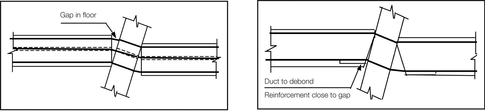
Figure 8: Gapping in floor Figure 9: Non-tearing floor
Recommendations
The Royal Commission recommends that:
14. designers give consideration to the use of the new technologies discussed above and described in the report ‘Base Isolation and Damage-Resistant Technologies for Improved Seismic Performance of Buildings’ in designing new structures to be erected in the Christchurch CBD; and
15. urgent work be carried out to enable appropriate provisions to be incorporated in the relevant structural design actions standards (AS/NZS 1170.0:2022, Structural design actions – Part O: General principles and NZS 1170.5 together with the material design standards (NZS 3101:1995, Concrete Structures Standard – The design of Concrete Structures, NZS 3404.1:2009, Steel Structures Standard – Materials, fabrication and construction and NZ 3603:1993, Timber Structures Standard) so as to facilitate the use of these technologies.
Annexure 1
Issue 1: Maximum Considered Earthquake Design Actions
a) Design for the Maximum Considered Earthquake (MCE) is mentioned in the commentary to the Earthquake Actions Standard, NZS 1170.5, where it indicates that material strain limits for the Ultimate Limit State (ULS) have been provided to give a margin of safety against collapse for the MCE limit state. However, the standard does not contain reference to this limit state or indicate where this limit state should be considered.
b) The return period for the MCE needs to be clearly identified for the different building classifications. Should the MCE be based on a return period of 2,500 years for all building classifications, or should this change with building importance?
See SESOC report sections 1.1 and 2.3 and Stairs report
Proposed actions
Introduce the MCE limit state into the Earthquake Actions Standard, NZS 1170.5 and identify how this limit state should be satisfied.
Additional background information on Issue 1
Structural Design Actions, Part 5: Earthquake Actions New Zealand, NZS 1170.5 defines the earthquake actions that need to be considered in design. Clause 2.1.1 requires that all structures comply with the requirements set out in the standard for the ‘ultimate limit state’ (ULS) and the ‘serviceability limit state’ (SLS).
The ULS is designed to provide a high level of protection against loss of life in a major earthquake (typically having a return period of 500 years, or more if the building has a high ‘importance level’). The importance level classification of buildings is set out in Structural Design Actions Part 0: General principles, AS/NZS 1170.0:2002.
The SLS provides protection against damage in an earthquake that has a return period which is generally of the same order as the design life of the structure. In the case of some buildings, classified as those with ‘special post-disaster functions’ (for example, major infrastructure facilities and medical emergency facilities) the SLS is raised to a return period of 500 years.
The commentary to NZS1170.5 states in clause C2.1, on page 9, that “[I]t is inherent within” NZS 1170.5 that “in order to ensure an acceptable risk of collapse, there should be a reasonable margin between the performance of material and structural form combinations at the ULS and at the collapse limit state.” The ‘collapse limit state’ is based on the MCE. The clause goes on to indicate that a margin of at least 1.5 to 1.8 is required. This comment suggests that regardless of the ULS return period the material strain limits required for the MCE are equal to a constant 1.8 (or 1.5) times the corresponding value given for the ULS, which implies that the return period for the MCE increases as the importance of the building (classification) increases.
Clause C1.4 of the commentary to NZS 1170.5 provides for ‘special studies’, which may be carried out to justify variations from specific provisions of NZS 1170.5. C1.4(d) gives as an example of special studies: “[d]etermination of maximum material strains for a specific detail shall be capable of dependably sustaining the deformations resulting from the design level event and having sufficient reserve capacity to contribute to a resistant system when subjected to deformations resulting from a very rare (2,500 year return period) event.” This indicates the MCE return period should be 2,500 years and that it is independent of the building’s classification. For normal commercial buildings with a return period for the ULS of 500 years, the 1.8 (or 1.5) factor implies a return period for the MCE design action of 2,500 years.
Setting material strain limits so that they satisfy the ULS and MCE conditions is logical for the majority of design of earthquake actions. An exception arises when designing elements that are sensitive to inter-storey drift or lateral deflection. Stairs are a particular case in point. At present the Standard contains no reference to, or requirements for, consideration of the MCE. Consequently the inter-storey drift limits for stairs are calculated based on ULS design actions. However, after a major earthquake rapid egress from buildings is highly desirable, particularly in view of the heightened chance of fire. It is important that stairs and other means of egress remain available for use, and as such it would seem logical that they be designed to sustain, without collapse, the displacements associated with the MCE actions. Likewise other structural elements that may cause the egress ways to be blocked should be designed to sustain the MCE actions.
Issue 2: Elongation in reinforced concrete members
Elongation, which occurs in structural concrete members when flexural cracks form, greatly increases when plastic hinges develop. This action has been observed to cause damage in beams, floors and potentially in walls. The damage in floors constructed with precast units to have been particularly significant with:
- wide cracks developing at the boundaries of the precast units preventing the floor acting as a diaphragm that transfers forces or restrains columns from buckling;
- the wide cracks inducing high strains in reinforcement leading to either failure of the bars or strain levels that call into question the remaining life of the reinforcement;
- a suitable design method required to enable design diaphragm actions to be established and to identify how such forces can be transmitted to the lateral force resisting elements making a rational allowance for the existence of the wide cracks; and
- in addition elongation in walls can increase the axial load carried by these elements.
See SESOC report sections 3.2.5; 3.2.6; 3.3.1; 3.3.6; 6.1.1.1 and 10.4.2.1 and Stairs report section 3.0
Proposed actions
Introduce information on the magnitudes of elongation in the Concrete Structures Standard, NZS 3101: 2006 and where wide cracks may be initiated due to elongation.
Recommend that research is initiated to establish a practical method for determining design actions in diaphragms.
Additional background information on Issue 2
Elongation of beams associated with the formation of plastic hinges has been observed and recorded in many structural tests of beams, columns and beam-column-slab sub-assemblies. In addition, a number of tests have been made of sub-assemblies consisting of floors, built up from precast units and in situ concrete, which are supported by reinforced concrete beams and columns. Under lateral loading, representative of seismic actions, elongation in the plastic hinges has resulted in wide cracks forming between the junctions of the floors and the supporting beams, and separation of some perimeter columns from the floors.
Observation of the seismic damage in the Christchurch earthquakes shows that the behaviour observed in the laboratories occurred in an appreciable number of buildings. In particular, wide cracks have developed and caused reinforcement to be strained to a high level and a considerable amount of mesh reinforcement fractured. In at least one case the connection of several columns to the floor slabs has been seriously weakened.
To enable rational design to allow for actions induced by elongation:
- design magnitudes of elongation associated with material strain levels in reinforced concrete members should be specified in the Concrete Structures Standard, NZS 3101: 2006;
- details should be given of where the resultant elongation induced cracks may be expected to form in a major earthquake and the implications this has for diaphragm actions in floors; and
- a rational method is required for assessing diaphragm forces that floors are required to sustain in design level earthquakes.
Issue 3: Performance of structural walls
Structural walls have not performed as anticipated from the results of structural testing. A number of issues need to be addressed as noted below:
- flexural cracking in walls in some cases has been limited to one crack, which has implications for the distribution and quantity of longitudinal reinforcement in walls;
- flexural cracking in walls in some cases has been limited to one crack, which has implications for the distribution and quantity of longitudinal reinforcement in walls;
- compression failure occurred in a number of cases in the outstanding legs of T and L walls;
- increased axial compression force associated with elongation; and
- significance of out-of-plane displacements acting on structural walls.
See SESOC report sections 3.3.5; 3.3.6; 3.3.7; 6.1.3.3; 6.2.1; 6.2.2 and 6.2.6
Proposed actions
Revise existing minimum longitudinal reinforcement requirements in the Concrete Structures Standard to give higher reinforcement proportions in the critical flexural tension regions of walls, and revise requirements for buckling restraint.
Recommend that research is initiated on the influence of elongation on axial forces in walls and on the significance of out-of-plane displacements being applied to structural walls sustaining in-plane forces.
Additional background information on Issue 3
In the Concrete Standard, NZS 3101: 2006, clause 11.3.11.2 (c), the minimum proportion of longitudinal reinforcement in beams and walls is given as √_ ƒ´c 4ƒy, which corresponds to a direct tensile stress in the concrete of √_ƒ´c 4. This is only a small proportion of the likely direct tensile strength of concrete, which could be of the order of 0.75√_ƒ´c if the supplied concrete has a compressive strength of close to 50 per cent in excess of the minimum specified value and a tensile strength that is consistent with an upper characteristic value. With the current specified minimum reinforcement proportions it could be anticipated that only one crack may form causing yielding of the reinforcement to be confined to a short length, potentially resulting in brittle failure. Concentrating longitudinal reinforcement in the critical tension zones of walls and beams should enable the tension force transmitted across cracks to be of a sufficient magnitude to cause additional cracks to form, thus allowing yielding to spread over an increased length of reinforcement so that ductile behaviour is achieved.
Current requirements for confinement of concrete in potential plastic hinge zones in walls are based on the length of the compression zone when it is subjected to maximum capacity design actions. However, under these actions high tensile strains can be induced in the mid region of a wall, which makes this reinforcement sensitive to buckling when the lateral forces decrease but the axial force remains. For this situation anti-buckling reinforcement may be required for stability of longitudinal reinforcement in the mid-regions of walls between the extreme tension and compression fibres. It should also be noted that with longitudinal reinforcement in tension in the mid region of a wall elongation is implied. Floors located above the plastic hinge zone may act to restrain this elongation by transferring forces to other vertical elements (columns or other walls). This restraint can greatly increase the magnitude of the axial force acting on a wall containing a plastic region. As this action is not considered in standard methods of analysis the design axial force in a wall sustaining a plastic hinge may be very significantly under-estimated, and hence potential crushing and buckling failures may not be predicted.
Tests on structural walls have in general been carried out by applying in-plane forces. However, in an earthquake, in-plane actions are invariably associated with out-of-plane displacements that induce out-of-plane shear and bending actions. While these actions are of a small magnitude, it is possible that they may have a significant effect on behaviour. The effect of these out-of-plane forces needs to be studied particularly in the situations where the distance from the neutral axis to the extreme compression fibre is an appreciable length of the wall. The likely adverse effects associated with out-of-plane actions and increased axial forces due to elongation can in part be reduced by providing structural walls with boundary elements.
A number of T and L shaped walls, which lack symmetry, have not performed as well as anticipated in design standards. Further study of these structural elements is required to enable rational design criteria to be developed.
Issue 4: Performance of stairs in multi-storey buildings
Stairs are required for egress after a major earthquake. Consequently it is proposed that they should be designed on the basis of the MCE. The Stairs report indicates that the inter-storey drifts found from previous and current design standards are inadequate to satisfy even the ULS. The report contains a number of recommendations on design actions for stairs in multi-storey buildings.
See the entire Stairs report and the SESOC report sections 1.1.3.1 and 2.3
Proposed actions
Recommend amendment of NZS 1170.5 to require stairs and access ramps to be designed to sustain the peak inter-storey displacements appropriate for the MCE limit state.
Additional background information on Issue 4
In the Stairs report it is noted that serious damage was sustained to stairs in an appreciable number of multi-storey buildings, which indicates that there is an urgent need to change design and construction practice for these elements. A review of previous loadings standards (NZS 4203:1976 to 1992, Code of Practice for General Structural Design and Design Loadings for Buildings) and the current standard (NZS 1170.5) indicates that there is a basic flaw in previous and current design criteria for stairs. The inter-storey drift that these elements are required to sustain does not correspond to the peak displacement implied by the design concepts on which the standards are based. Currently the design inter-storey drift is taken as a value that is appreciably smaller than the peak predicted drift. This arises from the use of the structural performance factor, Sp, to reduce the design level accelerations. In the commentary to NZS 1170.5 clause C4.4 states that “calculated loads correspond to the peak acceleration which happens only once and therefore are unlikely to lead to significant damage”. However, the peak displacement is linked to the peak acceleration, hence the use of the Sp factor gives an inter-storey drift that is less than the maximum value. It is strongly recommended that design criteria contained in NZS 1170.5 are amended to correct this anomaly and that stairs, access ramps and passages required for egress are designed to sustain actions associated with the MCE to ensure that they are available for egress in the event of a major earthquake.
Issue 5: Significance of vertical acceleration on seismic performance
In a number of clauses in the SESOC report it was indicated that research was required on the impact of vertical accelerations on structures.
See SESOC report sections 1.1.3.2; 3.1.7 and 3.3.4
Proposed actions
Recommend that research be initiated to determine the impact of vertical seismic ground motion on the performance of structures.
Additional background information on Issue 5
Recorded vertical ground motions in the Canterbury region indicate that there is a major mismatch between observed and design spectra for vertical seismic ground motion. The significance of vertical ground motion needs to be examined to see if current design criteria should be amended to require greater consideration for this action. The mismatch between current design spectra for vertical ground motion and observed spectra for vertical ground motion also needs to be addressed.
Issue 6: Behaviour of structural walls and beams
In an appreciable number of cases it was noted that the observed crack patterns in reinforced concrete walls and beams did not correspond to those observed in structural tests carried out in laboratories. In some cases the observed performance was poorer than expected. Several possible reasons have been advanced to explain this situation.
- In structural tests small cycles of displacement are applied and these are increased in subsequent cycles. The initial cycles may cause significant bond deterioration to occur, which by allowing slip to develop may reduce peak reinforcement strains considerably below those that would be sustained if the peak displacement had been applied near the start of the test; and
- In laboratory tests the concrete strength is generally well controlled. However, in practice the concrete strength can be very much higher than was assumed in design. The greater tensile strength can limit the distribution of cracks and consequently minimum reinforcement contents may be inadequate to ensure ductile performance. Research is required on loading sequences used in tests, which are not representative of all seismic conditions.
See SESOC report sections 3.3.7; 6.1.1.2; 6.1.3.1; 6.1.3.2; 6.1.3.3; 6.1.3.4; and 6.2.1
Proposed actions
Recommend that research is initiated to assess the significance of the sequence of loading on structural performance of structural walls and beams with reinforcement contents typical of construction practice.
Recommend that concrete strengths be assessed by taking cores, or other appropriate methods, from walls and other structural elements, where the crack pattern differs significantly from the anticipated crack pattern obtained in structural tests.
Additional background information on Issue 6
Since the early 1970s it has been common practice to test reinforced concrete structural elements under cyclic loading, where the magnitude of displacement cycles is progressively increased as the test progresses. With reinforced concrete members, at each inelastic displacement, the reinforcement yields at the critical section. For beam-column sub-assemblies this section is in the beams at the face of the column, while for walls and columns it is at the face of the foundation beam. The application of gradually increasing cyclic displacements has two effects:
- each time the bar yields it is forced to slip relative to the surrounding concrete, and this movement degrades the bond capacity over a length of bar, which increases yield penetration adjacent to the critical section; and
- the reversing load cycles reduce the shear resistance provided by concrete and this leads to diagonal cracking, which increases the length over which longitudinal reinforcement yields in a member (tension lag).
A consequence of this is that applications of gradually increasing magnitude of inelastic displacements during tests significantly increases the length over which longitudinal reinforcement yields, when the critical displacement is applied. For this situation the critical strain level in the reinforcement is reduced compared to that which would have been sustained if the major displacement had been applied without the initial inelastic load cycles.
Research is required to establish the significance of loading sequence on behaviour to see if current test results are representative of those that would be sustained where the peak displacements are induced at the start of the test, or earthquake, as was the case with the Canterbury earthquakes of 2010 and 2011.
Issue 7: Mesh reinforcement in existing buildings
Mesh in topping concrete placed above precast units or tray-deck type sections has been observed to fail in a number of buildings in a brittle manner. Due to its brittle characteristics doubt exists as to this material’s ability to safely transfer tension forces between structural elements.
See SESOC report section 3.2.5
Proposed actions
Recommend that where mesh has been designed to transfer forces, which are essential for the stability of a building, retrofit is carried out to ensure the critical forces can be transmitted by ductile reinforcement or other structural members.
Additional background information on Issue 7
Brittle failure of mesh was observed in several multi-storey buildings. This confirmed observations made in structural tests of the poor performance of this material in terms of its ductility. The brittle failure of mesh appears to have serious adverse effects on the stability of buildings in the Canterbury earthquakes, where it has been designed to transfer critical seismic actions to lateral force resisting elements.
