Interim Report Appendices
Appendix 1: Terms of Reference
Appendix 2: List of Expert Advisors
Appendix 3: Concepts Used in Seismic Design
Appendix 2
List of Expert Advisors
Andrew Buchanan, Professor of Timber Design, Department of Civil and Natural Resources Engineering, University of Canterbury
Desmond Bull, Holcim Adjunct Professor in Concrete Design, University of Canterbury
Athol J. Carr, Professor Emeritus, Department of Civil and Natural Resources Engineering, University of Canterbury
Misko Cubrinovski, Associate Professor Emeritus, Department of Civil and Natural Resources Engineering, University of Canterbury
Rajesh Dhakal, Associate Professor, Civil and Natural Resources Engineering, University of Canterbury
GNS Science, Wellington
Michael C. Griffith, Professor, Department of Civil, Environmental and Mining Engineering, University of Adelaide
William T. Holmes, Senior Consultant, Rutherford and Chekene, San Francisco, USA
Jason M. Ingham, Associate Professor, Department of Civil and Environmental Engineering, University of Auckland
University Institution of Professional Engineers New Zealand (IPENZ)
Ian McCahon, Principal, Geotech Consulting Ltd, Christchurch
John Berrill, Director, Canterbury Seismic Instruments
David Brunsdon, Kestral Group, Wellington
Michael Pender, Professor, Civil and Environmental Engineering, University of Auckland
Kevin McManus, Geotechnical Engineer, Nelson
Gregory MacRae, Associate Professor, Department of Civil and Natural Resources Engineering, University of Canterbury
New Zealand Society for Earthquake Engineering Inc (NZSEE)
Stefano Pampanin, Associate Professor, Department of Civil and Natural Resources Engineering, University of Canterbury
Jarg Pettinga, Professor, Department of Geological Sciences, University of Canterbury
Spencer Holmes Ltd, Civil and Structural Engineers, Wellington
Structural Engineering Society of New Zealand (SESOC)
Tonkin & Taylor Ltd, Environmental and Engineering Consultants, Christchurch
International Peer Reviewers
Norman Abrahamson, Adjunct Professor, University of California at Berkeley
Ralph Archuleta, Professor, University of California at Santa Barbara
Jonathan Bray, Professor, University of California at Berkeley
Bret Lizundia, Principal, Rutherford and Chekene, Structural and Geotechnical Engineers, San Francisco
Fred Turner, Staff Structural Engineer, Alfred E. Alquist, Seismic Safety Commission, California
Appendix 3
Concepts Used in Seismic Design
Structural actions
When a structural member, such as a beam, column or wall, is subjected to forces that are normal ( i.e. at right angles) to the span of the member, bending moments and shear forces are induced. These actions are internal to the member and are most simply envisaged by considering the actions at a cut in the member. The portion of the member separated by the cut is known as a free body, see Figure App 1(a) and (b).
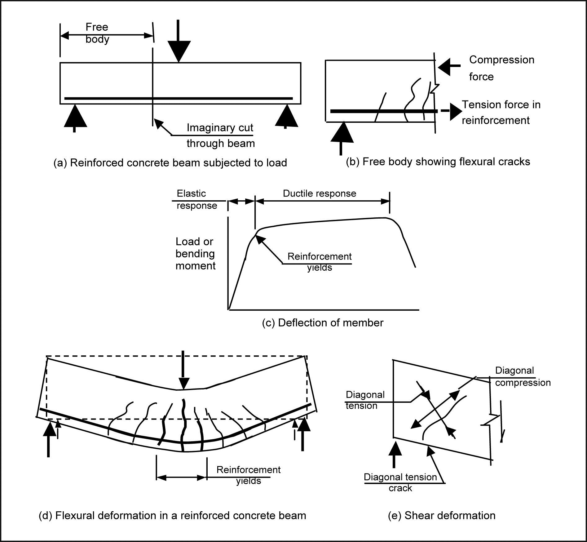
Figure App 1: Structural actions
Forces applied in a direction normal to the axis of a structural member cause it to bend. The internal actions associated with this action are known as a bending moment. Bending moments induce tension on one side of the members and compression on the other side. With reinforced concrete members, due to the low tensile strength of concrete, cracks form in the concrete subjected to tension. When these cracks are initiated the tension force previously resisted by the concrete is transferred to the reinforcement, see Figure App 1(b). If the forces are increased to a sufficient level the tension force in the reinforcement results in the stress in the steel reaching its yield point. At this stage any further increase in force results in the cracks widening and the deflection of the member increasing. Once yielding of the reinforcement occurs any subsequent increase in force on the member is small; see the load deflection diagram in Figure App 1(c). Figure App 1(d) shows a beam subject to a load which causes the reinforcement to yield. The ability of the member to deform without losing strength above the point where the reinforcement yields is referred to as ductile behaviour. The zone containing the yielding reinforcement is known as a plastic hinge or plastic region. The tensile strains in the reinforcement are greater than the compression strains in the concrete and as a result the member as a whole increases in length. This is known as elongation. Figure App 1(e) shows deformations associated with shear forces. The shear force is an internal force that acts in a direction normal to the longitudinal axis of the member, which is required for equilibrium. Shear forces induce deformation as illustrated in Figure App 1(e) with diagonal tensile and diagonal compression stresses. Due to the low tensile strength of concrete the diagonal tensile stresses can cause diagonal cracks to form. These are often referred to as shear cracks.
Seismic design of buildings
The description below gives a very brief outline of the concepts involved in seismic design of multi-storey buildings.
Current New Zealand practice is to design buildings to satisfy two sets of design criteria, serviceability and ultimate limit states.
The serviceability limit state involves designing the building to remain fit for its intended use in the event of an earthquake that has a magnitude of shaking that may be expected to occur, for normal buildings, once or twice during the design life of the building. Structures that may contain a significant number of people, or are necessary to provide essential services after a major earthquake, such as hospitals, are designed to sustain a higher level of seismic actions.
For the ultimate limit state the design criteria have been developed to ensure that in the event of a major earthquake life is protected. This is achieved by requiring the building to have suitable levels of strength, stiffness and ductility. The ultimate limit state criteria act to ensure that buildings subjected to earthquakes, which are greater than that assumed for the serviceability limit state, can be repaired, and that in earthquakes appreciably greater than that on which the ultimate limit state is based will not collapse and cause loss of life. For normal multi-storey buildings the ultimate limit state design actions are based on an earthquake with a return period of 500 years. For important buildings providing essential services the return period is increased and in some cases it reaches 2,500 years. Ensuring the building has adequate ductility is achieved through a process called ‘capacity design’. In conventionally designed buildings ductile behaviour is accompanied by structural damage.
Design seismic actions, consisting of forces and displacements that a building must be able to sustain, are specified in NZS 1170.5. The design actions for a proposed structure are determined from the nominated return period of the earthquake, the predicted dynamic characteristics of the structure, the seismicity of the region and the type of soils on which the building is founded. In Christchurch the soils consist of deep alluvial deposits of sand, silt and shingle. The dynamic characteristics depend on the periods of vibration of the building if it is left to freely oscillate. For the ultimate limit state the ability of the structure to behave in a ductile manner is also included.
The basis of capacity design is to ensure that in the event of a major earthquake brittle failure modes cannot develop. Ductile behaviour is obtained by designing the structures so that inelastic deformation is confined to identified locations, known as potential plastic hinges. This is achieved by designing all the structural elements outside the potential plastic hinges to have a higher level of strength so that inelastic deformation is confined to the chosen locations.
The potential plastic hinges are detailed to enable them to sustain the necessary deformation associated with the required level of ductility. A simple illustration of a ductile mechanism is shown in Figure App 2. The beam sway mode results in ductile performance while the high inelastic rotations induced in the columns with the column sway mechanism causes these elements to fail at a low level of ductility.
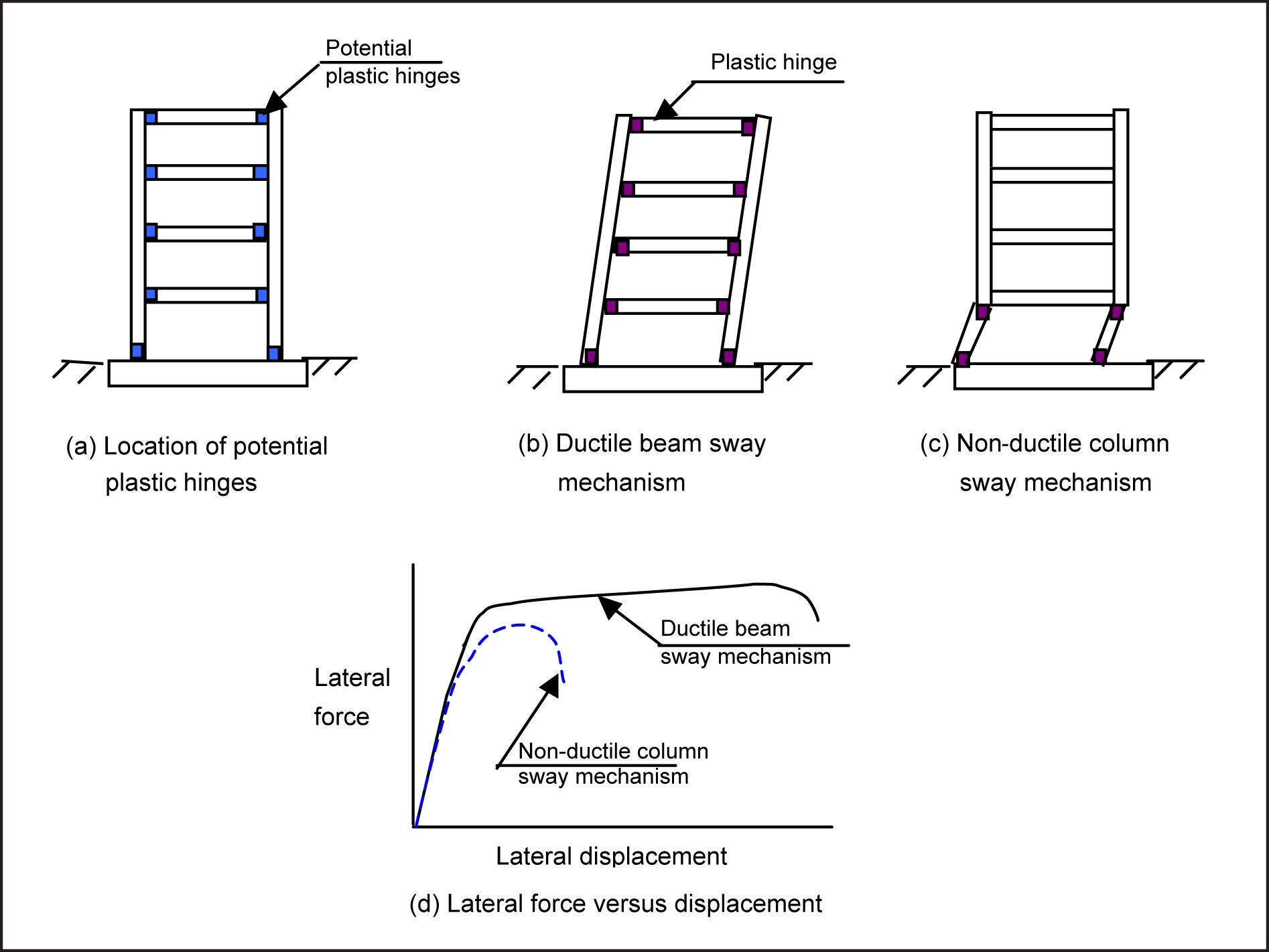
Figure App 2: Ductile and non-ductile sway mechanisms
Appendix 4
Glossary
| Base isolation | A means of limiting the seismic forces induced in a building by supporting the structure on devices that enable relative movement to occur between the foundation and superstructure when the force rises to a predetermined level |
| Base shear | Base shear is the shear force acting between the foundation soils and the building due to the inertial force induced in the structure due to the ground motion |
| Bending moment | See structural actions |
| Building classification | Buildings are classified in terms of importance levels 1 to 5 in AS/NZS 1170.0. Level 1 is for the lowest level of importance, for example, for isolated farm buildings. Level 2 covers most multi-storey structures, while level 3 is for buildings, which may contain a large number of people, such as hotels, offices and apartment buildings, or for buildings of 15 storeys or more. Level 4 is assigned to buildings required to be operational immediately following a major earthquake. Classification 5 is not covered |
| Diagonal cracking | Often referred to as shear cracking, see structural actions |
| Diaphragm | A structural element that transmits in-plane forces (diaphragm forces) to and between lateral force resisting elements. In buildings, floors usually act as, and are occasionally called, diaphragms. |
| Double tees | Precast prestressed units that are used in the construction of some floors |
| Earthquake-prone | The definition of an earthquake-prone building is given in section 122 of the Building Act 2004. In summary an earthquake-prone building is one that if assessed against current (new) buildings standards (NBS) would be assessed as not sustaining more than 33% of the minimum design actions for strength and ductility for the ultimate limit state |
| Earthquake risk buildings | A building is assessed as an earthquake risk building, if when assessed against the minimum requirements in current buildings standards, it sustains between 33% and 67% of the minimum design actions for strength and ductility for the ultimate limit state |
| Eccentrically braced frame | A structural steel frame consisting of beams and columns but with diagonal bracing in one or more bays that reduces the magnitudes of the bending moments in the beams. The short section of beam between the diagonal braces is subjected to high shear forces in a major earthquake and this zone yields in a ductile manner due to the high shear stresses |
| Element | A structural member such as a beam, column, wall or frame that is used to resist structural actions |
| Elongation | See structural actions |
| Hollow-core | Precast prestressed units that are used in the construction of some floors |
| In-plane and out-of-plane forces | Forces acting in the plane of a wall as distinct from out-of-plane forces, which act in a direction normal (at right angles) to the face of the wall |
| Low damage or damage avoidance design | There are a number of methods for reducing the structural damage sustained in major earthquakes; base isolation is one of these and the PRESSS and non-tearing floor systems are two other methods that may be used |
| Maximum considered earthquake (MCE) | Generally taken as an earthquake with a return period of 2,500 years. Multi-storey buildings designed to current New Zealand Standards are intended to have a small margin of safety against collapse in the MCE |
| Moment resisting frame | A structural frame consisting of beams and columns which is designed to provide lateral force resistance to the buildings |
| New Building Standards (NBS) | The building standards in force at the time when an assessment of an existing building is made |
| NZ Standards (NZS) | Sets of rules that are used in the design of buildings. The Earthquake Actions Standard (NZS 1170.5) defines the required combination of strength, stiffness and ductility that a proposed building must be designed to contain, while the material Standards for Structural Concrete, Structural Steel and Structural Timber Standards provide rules on how these requirements can be satisfied. |
| Period | The time in seconds it takes for a structure to complete one oscillation. Frequency is the inverse of period, that is the number of cycles per second |
| Potential plastic hinge | See structural actions |
| Precast Structural Seismic Systems (PRESSS) | Precast concrete members (beams, columns or walls) are stressed together by unbonded prestressed cables which causes the structure to spring back to its original position at the end of the earthquake |
| Response spectra | The peak accelerations (or displacements) with the period of vibration of structures due to an earthquake or a design earthquake |
| Return period | The average time in years between earthquakes of a given magnitude on a fault or in a locality. The magnitude of the earthquake and the associated actions are assumed to increase with the return period. Hence the design actions for an earthquake with a return period of 2,500 years is assumed to be 1.5 (or 1.8) times the corresponding values for an earthquake with a return period of 500 years |
| Seismic design | See appendix 3 |
| Serviceability limit state | See seismic design of buildings |
| Shear force | See structural actions |
| Shear wall | A structural wall that is used to resist lateral forces induced by earthquake actions, sometimes referred to as a structural wall |
| Single degree of freedom | A simple structural model that can only vibrate in one mode |
| Strain | The change in length divided by the original length |
| Stress | Force divided by area of element resisting the force, i.e. stress in reinforcement is equal to the force carried by the reinforcement divided by the area of reinforcement |
| Structural actions | See appendix 3 |
| Ultimate limit state (ULS) | See seismic design of buildings |
| Unreinforced masonry (URM) | May consist of brick buildings or buildings built using stone masonry |
ISBN: 978-0-477-10344-2 (paperback)
ISBN: 978-0-477-10345-9 (pdf)
Canterbury Earthquakes
Royal Commission
PO Box 14053
Christchurch Mail Centre 8544
Christchurch
New Zealand
0800 337 468
+64 3 741 3000
canterbury@royalcommission.govt.nz
Return to Contents | Go to Section 3.5 | Go to Interim Report home
